Technical information

There are a number of sources for technical information on the early M24 Gold Stars, Including the BSA Service Sheets which are listed below. There is also the BSA WDM20 website http://wwww.wdbsa.nl which has an excellent technical section.  Although the website is concerned with the BSA Military M20 side valve machines, many of the engine, gearbox and cycle parts were shared with other BSA machines  including the M24 Gold Star.

                                        1938 BSA JM24 Engine

1. General Data           
2.  M24 Cams 
3. Colour scheme 
4. Electrical equipment    

5. Wiring diagrams
6. Gold Star Screw threads
7. Gearbox and Sprockets number of teeth
8. Transfers
9. Gaskets  
10. Bearings
11. Bush and shaft diameters (service sheet No. 702)
12. Mudguards and stays
13. Crankshaft balance factor.
14. 'Sensible' improvements (the BSA clutch)
15. BSA workshop tools
16. BSA Service sheets

KM24 engine 1939


1)  GENERAL DATA 

Engine
:  Single port, 496cc OHV single cylinder.    Bore 82mm,  Stroke 94mm.              
                  Compression ratio 7.75:1       (Option of 12.5:1 with High Compression Piston)              
                  Power output 29-30bhp @ 5,800rpm              
                  Alloy cylinder head with cast-in bronze thread inserts, and screwed-in steel valve seats.              
                 Alloy cylinder barrel with pressed-in steel liner
                 Valves:        Inlet:       length 4.21875in Head Dia 1.65625in Stem Dia 0.34375in
                                       Exhaust: length 4.21875in Head Dia 1.59375in Stem Dia 0.375in
               

Ignition:     Lucas MO1 Magdyno with manual advance.    Ignition timing 7/16in (11mm) BTDC on full advance


Carburettor: 1938:  Amal 10TT36 1 & 5/32” bore, Main Jet 370, Throttle valve 5, needle groove 4          
                           1939:  Amal 10TT38  1 & 5/32” bore, Main Jet 350, Throttle valve 6, needle groove 4

Transmission:
Gearbox: 4-speed,  enclosed footchange, external clutch release lever
                    Magnesium Alloy (Elektron) gearbox cases for 1938 only
                    Close-ratio gears for 1939, with option of standard wider ratios  
                 Ratios:
                1938 & 1939 standard:    1st   14.3:1      2nd   9.9:1      3rd    6.3:1       4th   4.8:1                      
                1939 Close ratio:               1st  11.85:1    2nd   8.3:1     3rd  5.25:1      4th  4.8:1
               
Clutch: 6-spring wet multiplate with 43 tooth chain wheel, driven by ½ x .305in single row primary chain from 21 tooth 4-lobe cush-drive engine sprocket.
                18 tooth gearbox sprocket, 
driving 42 tooth rear wheel sprocket via 5/8 x 1/4in. final drive chain.

Frame: Reynold 531 high-tensile tube.  Single front down tube, rigid rear. No sidecar lugs.  KM24 has a side stand lug fitted to the rear frame.
               BSA single spring girder front forks, also in 531 tube.

Wheels:  20in WM1 front, (21in WM1 on Competition Model), 19in WM3 rear.  JONES rims fitted to BSAs

Tyres: 
3.00 x 20in  Front      3.25 x 19in Rear 1938     3.50 x 19in Rear 1939


Brakes
:  7in Single Leading Shoe drum brakes front & rear.


Petrol Tank Capacity
: 3 Gal. (1938)  3.5 Gal. (1939)


Oil tank capacity:        
4 pints (1938)   5 pints (1939)

Wheelbase
54 inch       Saddle Height: 28.5 inch    Ground clearance:     4.625 inch     Dry Weight:     345lb 


2) BSA M24 Cams
1938
:  
inlet cam is numbered 66-2086, exhaust 66-2087. The number is stamped on the outer end of the shaft.
The inlet cam 66-2086 is the same for M24 & M23, but the exhaust cam is unique to the M24.
38 BSA cams differ from later ones as the cam & shaft are one piece, and the pinion is keyed onto the shaft.
The cam shaft rotates on inner bushes in the crankcase, and outer bushes in the timing cover. 1938 cams are not interchangeable with later ones.
1939
:  
cam & pinion are one piece, and bushed to rotate on a separate shaft pressed into the crankcase. Cams and timing pinion are held in place by a steel outrigger plate mounted on
the crankcase beneath the timing cover.

Inlet & exhaust cams are interchangeable, the part number being 65-2420. The same cams are used in all 1939 BSA M and B series engines, except B21 & B23 Standard, and the M22.
65-2420 continued in use for  IN & EX in the WDM20, and 1946-59 post war M20,M21, B31 & B33.
The post-war Gold Stars from 1949 used a variety of different cam profiles, details of which can be found in “The Gold Star Book” published by Bruce Main-Smith in 1974.
These will all fit 1939 M24 engines, and a suitable combination can produce a worthwhile improvement in performance.  

3) Colour Scheme
JM24 - The first Goldstar had a black and chrome finish. The chromium Tank had a matt silver centre panel which was lined with two pinstripes (thick and thin) in Black. 
The chrome oil tank also had a matt silver panel with the pre war BSA piled arms logo.  The mudguards were black (competition models chrome) and wheel rims had a black centre stripe,
which was lined in gold.

KM24 - The 1939 model had a black and chrome finish, but in this case the matt silver panels of the petrol tank and the matt silver centre stripe on the wheel rims were lined in maroon. 
 Again the petrol tank had two pinstripes, one thick and one thin.  The oil tank, tool box and rear mudguard were lined in gold.

4) ELECTRICAL 
EQUIPMENT (lucas)
Magdyno -  MO1 
Magneto (Competition or racing, Lucas KN(R)1 or BTH TT models)

Dynamo - E3HM
Voltage control Unit - MCR1
Headlight - DU142
Rearlight - MT110
Ammeter - Lucas type CZ 27
HORN
JM24 1938 - HF 1440
KM24 1939 - HF 1441

SADDLE - S707  Made by Herbert Terry and Sons Ltd. 

SPEEDOMETER  and also the front wheel speedometer drive - made by (Jaeger) Smiths industries - 120mph 5/36/1/3
(Original speedometers had the more complex 'pin drive' rather than being secured to the drive cable by a screw on bezel.
The change from pin to bezel occured 1939/40 and most, if not all, original equipment speedometers on the M24 would have been the pin type)
The instrument case did not have provision for an electric light.  An illuminated speedometer was an optional extra costing £5

TYRES - Dunlop Rubber Co. Ltd.,

CARBURETTERS - Amal LTD.,


5) Wiring Diagrams:
The wiring layout differs between 1938 and 1939 models in that lighting switch and ammeter are located in the headlamp in all JM24 bikes and KM24 competition models, and in the petrol tank panel in standard KM24 models. Lucas also switched to colour coded wiring in 1939, earlier models having all black wiring with coloured tracer rings on the end of each wire. 
      

v
1938 Wiring Diagram
1939 Wiring Diagram

Fixings

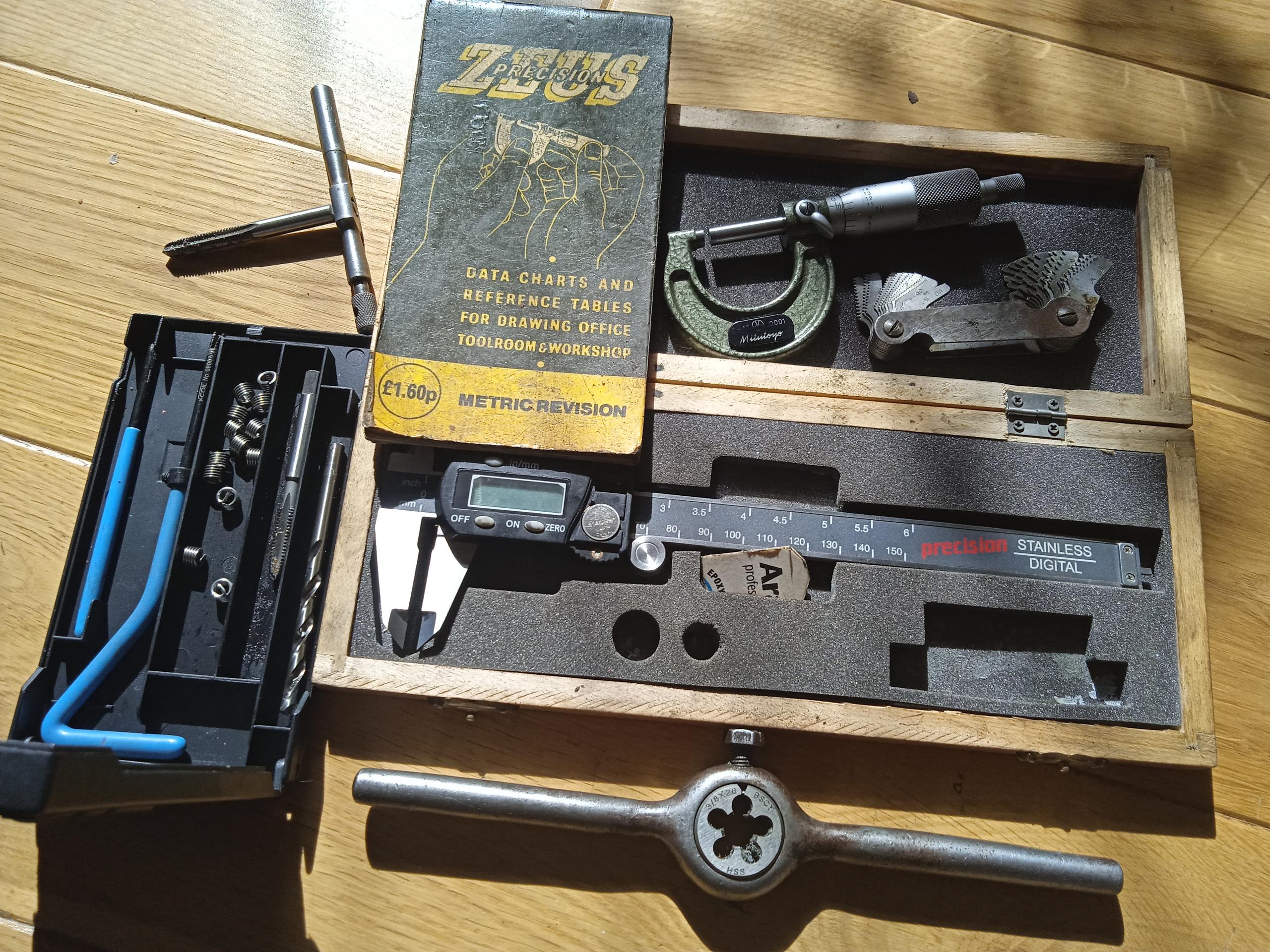
6) GOLD STAR SCREW THREADS Reproduced below is an article by Jon Luke, Technical Officer from the GSOC Gold Star Owners Club. It has been adapted from Jon's work, which focused primarily on the later 1950's and 60's Goldies.  The majority of threads on all Gold Stars (pre and post war) are BSC or 'Cycle' thread, with BSW or 'Whitworth' used  on odd larger threads and stud fixings into aluminium engine and gearbox casings.  Lucas electrical equipment and some handlebar fixings use smaller BA 'British Association' threads.  Many threads and fixings are found on the later Gold Stars and a later parts book or the excellent BMS 'The Gold Star book' can be useful when checking part numbers.  It is common to find evidence of repairs made with what ever was available at the time.  It is however better to repair or restore an original un modified bike, with the correct threads and fixings.  Jon says it is worth investing in some measuring equipment and also taps and dies for the more common sizes, so studs, nuts and bolts can be repaired or remade.  Stainless steel thread repair insert kits can be bought which provide a way or repairing threads in aluminium casings, and as an alternative to welding up the damaged thread hole and re-tapping to the correct size.
GOLD STAR SCREW THREADS – A GUIDE Many have asked the question ‘How many different threads can you have on one motorbike’, and there does seem to be ongoing confusion on this point. All the threads on a Goldie are the old imperial types to the British Standards of the day.  Given that the imperial threads have been out of production for 60+ years now, very few of us are now left who used and understood them in the day. This article is a guide to understanding and identifying the threads on your Goldie so that you can deal with them accordingly, even down to ordering the right taps and dies for repairs.                                                                                      British Standard Cycle (BSC) or just ( Cycle)  is a fine thread, these are sometimes known as Cycle Engineers Institute threads (CEI). This thread form is very common on Goldies and covers the great majority of the threads found. This thread will be found in all diameters from 3/16 inch upwards, and it comes in two pitches namely fine at 26 TPI and course at 20 TPI, simple as that!   All the large threads such as the clutch nut, crank shock adsorber nut, wheel spindle threads etc, etc, will be BSC cycle in either 26 or 20 TPI pitches, this includes certain light alloy threads such as the telescopic head bolts into the crankcase. British Standard Whitworth (BSW)  is a course thread and most suited to soft materials and is used on Goldies for pretty much all the threads cut into light alloy parts. Imperial thread pitch is measured in ‘threads per inch’ and diameter in inch fractions, so in light alloy parts expect BSW threads in the following sizes and pitches, 3/16 x 24,  ¼ x 20, 5/16 x 18,  3/8 x 16,  7/16 x 14.  The next series of threads that you will encounter are BA (British Association)  threads which are used on smaller components and come in 11 sizes. where 0BA is the largest at about 6mm diameter down to 10 BA which is tiny and will only be found inside fine instruments such as the speedo and the ammeter. On a Goldie they are almost exclusively used on electrical equipment although the 0BA is widely used on Amal handlebar controls and there is some BA in the carbs.  British Standard Pipe threads (BSP) these are weird at first sight but make sense when explained, these will be found on some Goldie pipes notably the engine oil pipes and the fuel pipes. These threads are dimensioned around the cross bore of the hole through the thread that the fluid passes, so a ¼ BSP thread has a diameter of .518 inch and is 19 TPI, to allow a ¼ inch diameter fluid passage through the thread. In addition to the ¼ BSP mentioned, you will find 1/8 BSP on some fuel taps, this is .383 inch diameter x 28 TPI. Also on some fuel taps you will find 3/8 BSP which is .656 inch diameter x 19 TPI. Note here that fuel tap to tank adaptors may be found which are 1/4 BSP-3/8 BSP.         The other specialist sector thread series to be aware of is the Model Engineers (ME) series, like BSC Cycle these come in all fraction sizes with a 32 TPI course series and a 40 TPI fine series. The only use that I’m aware of on a Goldie is a 40 TPI ME thread on the GP (TT) carburettor pilot fuel screw.                                                                                                                                                                                                                                                                                                                                  'The Whitworth BSW standardised thread form came complete with a standardised series of hexagon (nut) sizes. The hexagon sizes mostly found are .445 inch across flats (AF),  .525 inch AF,  .600 inch AF,  .710 inch AF with some bigger and smaller sizes found occasionally. The AF size relates to the bolt diameter but this relationship varies according to the thread type. For example .525 inch AF is the correct size for ¼ inch diameter Whitworth bolts, but correct for 5/16 inch diameter BSF bolts, hence a .525 spanner is marked ¼ and 5/16 on the jaws. BSC Cycle threads follow the BSF pattern of hexagon (nut) sizes, but there are exceptions where the next hexagon size down is used for space and appearance reasons. Two obvious examples are the handlebar clamp bolts which are .445 inch AF instead of the .525 inch normally used for 5/16 inch thread diameters. So there you have it, it really is as simple as that!!!!!!!.                                                                                                                        

 I suppose that the obvious question here is that if all this stuff has been obsolete for 60 years, how do we get spares and repairs done? Simple answer is that all the taps and dies in all these sizes are readily available new and to good quality at economic prices so never really an issue once you know what you need. Several suppliers are in the business but far and away the most comprehensive and efficient is Tracy Tools of Torquay in Devon, see their website and speedy ordering service. Two other useful bits of kit worth having with regards to threads are a set of thread gauges, these are like feeler gauges except that each piece has a thread form cut in one side and is marked with the TPI number. The gauges are offered up to the thread to be measured and a match found which tells you the TPI accurately. The other useful item is a Zeus Precision Book of Thread tables, this is pocket sized on plasticated paper for workshop use. A small digital caliper is also handy to get your bolt diameter right although you will need to convert the decimal diameter to a fraction.                                                                                                                    

GOLDIE SCREWTHREAD DETAILS -AS FOLLOW:  Screws and studs tapped directly into  aluminium (with exceptions) are 3/16 inch x 24 TPI BSW, 1/4 inch x 20 TPI, BSW,  5/16 inch x 18 TPI BSW,  3/8 x 16 TPI BSW  Engine mainshaft – cush drive nut ¾ inch x 20 TPI BSC Timing side shaft 1/2 inch x 20 TPI BSC Crank pin 7/8inch x 20 TPI BSC )Magneto pinion (extractor thread 11/16inch x 20 TPI BSC Magneto spindle 3/8 inch x 20 BSF,  Valve lifter sleeve ½ inch x 20 TPI BSC, Timing cover relief valve KM 3/8 inch x 20 TPI BSC Crankcase - oil pipe adaptors 3/8 inch x 20 TPI  BSC,  Gearbox mainshaft – clutch end 5/8 inch x 20 TPI BSC Gearbox mainshaft – selector end 9/16 inch x 20 TPI BSC Gearbox – sleeve gear 1 7/32 inch x 24 TPI BSC  Gearbox selector shaft 7/16 inch x 20 TPI BSC  Gearbox drain plug 7/16 inch x 20 TPI BSC Gearbox inspection cover 3/16 inch x 24 TPI BSW,  (Rear brake anchor ½ inch x 20 TPI BSC,  rear wheel/brake drum spindles 9/16 inch x 20 TPI BSC,  rear wheel spindle 9/16 inch x 20 TPI BSC,  or rear brake spindle 7/8 inch x 20 TPI BSC, further checking of data required ) – Steering head adjusting sleeve  outer 1 5/16 inch x 24 TPI BSC Steering head adjusting sleeve – inner 1 1/8 inch x 24 TPI BSC,  Touring footrest stud ½ inch x 20 TPI BSC Fuel taps – small thread (1/8 BSP) .383 inch x 28 TPI BSP Fuel taps larger thread, oil pipes, fuel pipes (1/4 BSP) .518 inch x 19 TPI BSP Fuel taps very large thread, fuel tank boss (3/8 BSP) .656 inch x 19 TPI Some Amal handlebar controls 0 BA Some Amal equipment & Lucas equipment 2 BA and 4 BA Spark Plug 14mm x 1.25 mm pitch TRAPS FOR THE UNWARY Thread angle is the angle between the flanks of adjacent threads, and it varies according to thread form. BSW, BSF and BSP have an angle of 55 degrees, while BSC threads of 26 TPI have a 60 degree angle, and BA is 47.5 degrees. ¼ x 26 BSF and ¼ x 26 BSC are consequently not interchangeable although how to tell a ¼ BSC from a BSF is impossible and they don’t fit together too well. The trick here is to buy ¼ BSC taps and to just run through any new nuts before use.  A further complexity is that the BSC x 20 TPI threads have the Whitworth thread form with the 55 degree thread angle! There is a similar problem with 0BA which is 6mm x 1mm thread pitch, while a 6mm metric coarse thread is also 1mm pitch, these are again not interchangeable since the metric thread angle is 60 degrees. Care is needed with Amal handlebar controls where original equipment is likely to be 0 BA, while replica parts could be 0 BA, but more likely to be 6 x 1 mm metric coarse. It is an inescapable fact that some manufacturers of replica parts, particularly in the far east, just might not have read British Standard 811:1950 Revision lately. Consequently, new parts with the right thread and the right diameter might not fit properly, I saw an instance with a replica Triumph clutch conversion securing nut recently. The solution here is to recognise that the finer details of acceptable manufacturing tolerance have been lost in the mists of time and that you might well need to buy the taps and dies and run the threads through before use. 

TIP  The BSA 'reduced head', handlebar bar fixing bolt 5/16 BSC, can be usefully adapted with those with access to a die, and or a lathe, for several other applications such as headlamp, headlamp stays, mudguard stays and mudguard fixing bolts.


Measuring tools and tools for making threads.

From top left: Tap and tap holder, Zeus tables (or internet), Micrometer, Thread gauges, Digital vernier, Die and die holder,  Insert/thread repair kit.

7) Gearbox and sprockets: number of teeth

Sprockets and Gearbox pinion teeth for M-Series and Post War early B Series


Standard M-Series

JM and KM 24

Close Ratio

KM24

Post War Gold Star

(for information)

Post War Gold Star

(for information


Engine Sprocket

(16,17,18,19,20 also)

21

21


Clutch Chainwheel

43

43


Gearbox Sprocket

(16,19 also)

18

18


Rear Sprocket

42

42


Medium close: Scrambles

Extra close: Road racing

Mainshaft


1st C

16

16

18

19

2nd C

20

20

22

23

3rd B

25

25

25

25

4th A

28

26

28

26

Layshaft


1st F

29

29

27

26

2nd E

25

25

23

22

3rd D

20

20

20

20

4th D

17

19

17

19


*Speedometer drive front hub drive ring 70T,  Speedo gearbox  23T*

BM 4/24


8) Transfers                                                                                              BSA transfers are readily available. The JM24 Gold Star had the early 'large' Gold Star transfers on the petrol tank, and a large 'piled arms' transfer on the oil tank. There was also a BSA pre 53 'garter' transfer on the headstock,  the earlier one with the lighter background,  The 1939 KM24 had a pre 53 garter transfer on both the oil tank and the headstock, which was the one with the darker background.

BSA 'piled arms'

Larger size used on 1938 JM24 toolbox.

BSA Pre-53 light background (6072)

Used on 1938 JM24 headstock. In practice, when applied, it is difficult to notice the difference between the two different garter transfers when applied to black painted surfaces.

BSA Pre-53 dark background (6073)

Used on 1939 KM24 for the toolbox and  the headstock.

9) BSA JM24 1938 and KM34 1939 Gaskets

(Gaskets marked* are common to other M or B group machines)


Note: Pre war Gold Star ‘gaskets’ (or washers according to the parts books) which are not common to other models are now virtually unobtainable.   It is worth retaining any used gaskets for a ‘pattern’ so new gaskets can be made from ‘gasket paper’ obtained from a ‘Motor factors’ or ‘auto parts store’.   Copper head gaskets may be re-used, or made from sheet material which needs to be annealed before use.   ‘Wellseal’ jointing compound can be used for the cylinder head to cylinder barrel joint. The fibre washers used for drain plugs can be bought from auto stores,  and off the internet.


Name

BSA Part number

Notes

Cylinder head ‘washer’ or gasket

66-189

Copper

Cylinder base washer

66-192

Paper (B34 is similar)

Rocker box top cover joint washer

66-344

Paper

Rocker box cover front joint washer

66-326

Thick card

Rocker box (valve chest) joint washer

66-325(2)

Thick card

Timing cover joint washer *

99-1909

Common to all 40/50’s M&B group machines.

Tappet cover joint washer (JM24)

66-1932

1938

Tappet cover joint washer(KM24)*

66-1937

1939 onwards M&B Group

Crank case scavenge (sump) cover washer*

66-2612 (2)

Common to all 40/50s M&B group

Gearbox outer cover joint washer*

66-3068

Common to WDM20 etc.

Gearbox inner cover joint washer*

66-3069

As above

Gearbox inspection cover washer*

15-4110(2)

As above

Mainshaft felt washer*

24-4232


Gearbox oil filler plug washer*

M196a


Chaincase and crankcase joint washer*

66-7575

As above

Chaincase rear felt washer*

15-8814

Felt

Chaincase joint washer*

66-7514

Cork

Chaincase oil level plug washer*

EB242


Chaincase inspection cap washer*

27-207


BM 9/23


M24 Gaskets

10) Engine Balance:  It maybe necessary to fit a different connecting rod or piston to a BSA crankshaft assembly.  I have not found any published information on the JM and KM24 long stroke engines.  Experience has shown that a 54 degree balance factor works well.  

 11) BSA M24 WORKSHOP DATA BEARINGS from SERVICE SHEET 703


Location

BSA Part No.

Hoffman No.

Skefko No.

Ransome & Marles No.

British Timkin No.

Fischer No.

Crankcase Roller Bearing D/S

24-724

R.325L

402454.B

MRJA.25

-

MFM.25

Crankcase Ball Bearing D/S

24-732

325

6305

MJ.25

-

6305

Crankcase Roller Bearing G/S

24-722

RM.9L

CFM7/C2

MRJA7/8

-

RFM.9

Crankpin (big end)

See details below


Gearbox ball journal

24-4217

L.S.8

RLS.6

LJ3/4

-

LS.8

Gearbox sleeve gear

24 065

135

6207

LJ.35

-

6207

Wheel bearings (taper roller)

24-6860


2K.1178X

2K.1130X1


1178.X

1130.N1


BM 10/23

Big end bearing
 
 
66-0490     Conrod liner / big end bearing outer race
 
66-0545     Crank pin
 
66-0503     Bearing cage
 
24-0375     Big end rollers  x  24
 
31-0298     Crank pin nuts   x   02
 
65-0479     Crank pin screw
 
31-0300     Big end nut lock washer   x  02
 
02-0077     Big end washer screw
 
66-0491     Small end bush
 
02-0036     Crank pin key (pre- war number EA 0101)
 
 
The reference number for the ALPHA bearings big end bearing complete is B14.
 
Some WD M20 models had a big end bearing with no cage.
 
This is known as the crowded roller type.
 

12) M24 Goldstar Mudguards and stays

The two model years have different mudguards and the BSA parts books are a little

unclear in that an upright stay (to support the pillion pad area of the mudguard) is

not listed for the 1938 bike although it can be clearly seen in some pictures and

Photographs. The upright stay is listed in the 1939 Parts Book.


Description                                                                    JM24                     KM24                                                    Competition                            Notes

Front Mudguard 

66-6529
(5 inch)

66-6532 (5.5 inch)

(wider with indents for fork)

66-6555

B25 comp

65-6521 (4.5 inch)

Competition guard has two pressed mounts

for the mumber plate brackets, and the rib is 

also missing for the fixing area to the fork. 

Valanced type

15-7153

65-6534


Front Mudguard stay

66-6540

66-6540

65-6522 and B25 comp


Rear Mudguard

66-6737

66-6940

Valanced

66-6872 JM

66-6950 KM

65-6787 B25

M24 comp similar to B25 (6 inch flat section
with central rib)

Rear Mudguard

Tail

66-6739

66-6941


Upright stay

(See notes)

66-6945

(2)

65-6804

No upright stay listed but clearly fitted on 

some machines to support area of

the mudguard pillion pad

Bottom stay

66-6891

66-6891


(left and right)

Lifting stay

66-6884

66-6884

65-6805

M24 comp same as B25

Front Stand

66-4727

66-4727

65-4693/3


Front stand for valanced type mudguard

66-4729

66-4729


13)  Sensible improvments: The BSA clutch                                                                                                                               

The BSA 6 spring clutch is prone to wear, clutch drag and slip.  Sometimes all at the same time!  Replace any parts which have suffered wear or from heat distortion.   A popular modification has been to fit the superior Triumph/BSA 4 spring clutch with the required centre adaptor.  There are two types. the mainshaft taper angle is the same, but the diameter of the taper is different. The larger diameter taper is correct when fitted to the earlier box. The swinging arm type is smaller.   Care is needed to ensure correct primary chain alignment, check with a straight edge.  If there is poor alignment adjustment will be needed, or there will be premature wear of the clutch basket and the sprockets. The advantage of staying with  a chain primary drive, rather than a belt drive, is that it is easy to change gear ratios by swaping the engine sprocket for one with fewer, or more, teeth.  It is possible to change from a four lobe to a later two lobe cush drive but for every day use  the 4 lobe is just fine.  


For information: An alternative clutch modification, which was popular with racers and competition riders using later gearboxes in the 50/60s, was to fit a Norton 3 spring 'Dominator' type clutch.  The Norton clutch is very good (better than the 4 spring Triumph) and has an internal 'splined' centre which will fit with the early BSA A7 twin  'splined' gearbox mainshaft, if one can be found.  It is a straight swap, and was marketed by Eddie Dow as a very useful modification for owners of the post war models.


14) BSA Workshop tools

1) BSA headset threaded bearing removal tool.  Useful! but in practice an alternative removal method involves welding  a piece of metal, across the bearing 'race ' and then using a hammer and drift to knock the race or track out.

Clutch tools

BSA 6 spring clutch locking tool, made from three scrap clutch plates, and also a BSA clutch extractor.

Press tool

Made to form curved flat ends of mudguard stays using either a (large) engineers vice or better a hydraulic press.

Cush Drive Nut tool

Made from a scrap nut and a 1/2 drive socket. used for loosening and tightening.  A better option than using a 'C' spanner or a hammer and drift.

Magneto pinion extractor

Essential for removing mag pinion.  Later Goldie pinion with peg for timed breather and tacho drive shown

Magneto pinion tightening tool (1938 JM24)

A damaged timing cover, or a made up plate, can be  used to hold the otherwise unsupported JM24 camshafts while the magneto pinion nut is tightened.

15) BSA Service sheets (can be downloaded from internet)

BSA Service sheets (relevant to M24 Gold Star)


Number

year

Subject

63d

1938

Piston rings

63e

1938

Warning piston rings 37-1938

82

1938

B&M Group machines, oil in primary chaincase

84

1938

Cylinder liners

86

1938

Cylinder liners and pistons

93

1938

Gear ratios

94

1938

Home Carburettor settings 1939

91

1938

Sparking plugs (KLG 831)

92

1939

Ignition timing

133

1937- 8

Conrod and Bigend

304


Engine complete dismantling (B)

305


Reassembling engine (B)

308


Clutch

539

1938

Carburettor settings

540

1938

Sparking plugs

541

1938

Ignition timing

542

1938

Gear ratios

602


Gearbox exploded view

603


Lubrication system (B,C&M

604


Engine adjustments (B&M)

606


Removing engine from frame and complete dismantling

607


Reassemnling the engine

608


Gearbox and gearchange

609


Transmission

611-612


Brakes and Hubs relining

613


Adjustments to Steering head and forks

514- 706


Front Forks

701


All models useful data

702


workshop data (bushes)

703


Workshop data bearings

704


Piston clearances

705


Periodic attentions

709


Fault finding

710


Chain alteration and repair

731

1938-52

Service tools

802


Ignition system Magdyno

804


Voltage Regulator unit

805


Battery

806


Lamps

807


Electric horn

808


Electrical wiring system - earth

808A


Wiring diagram + earth


Rigid frame B&M adjustment, dismantling and re-assembly of the rear hub and brake